You are using an out of date browser. It may not display this or other websites correctly.
You should upgrade or use an alternative browser.
You should upgrade or use an alternative browser.
the Open Source hardware thread
Shah
Cyborg Agent
check 2 with steady power at ir led. dont put any frequency, does it glow through video cam ?
No. It's not glowing still. I will get another IR LED today and check if it works. If the new one works, then the problem is with the IR LED otherwise with my circuit.
Shah
Cyborg Agent
i think the led is bad.
anyways if u put 5v at 555, the output is normally 1.7 -2v lower than the input, so, use some 1k-2.2k resistor to limit current through led. or it may burn up.
Gonna get some IR LEDs today. Will check them with 1k resistor.
EDIT: Can you suggest some online stores where I can find all the components?
Last edited:
Shah
Cyborg Agent
Bhasha e-Store - Bhasha Technologies e-Store
Ventor Technologies India, Online Electronic Component Shop
i purchased from ventor before they ship quite fast, i hope they are reliable.
Thanks.
Shah
Cyborg Agent
i think the led is bad.
anyways if u put 5v at 555, the output is normally 1.7 -2v lower than the input, so, use some 1k-2.2k resistor to limit current through led. or it may burn up.
With a new LED in place, It seems working. But, It isn't emitting at 38kHz. Any other circuits to make the IR LED to emit at 38kHz.
Shah
Cyborg Agent
have u tried measuring the actual frequency of the 555 output ?
No. How do I do that?
BTW, I am thinking of using variable resistors.
OP
icebags
Technomancer
lemme write u a sketch :
1) make sure the 555 o/p is less than 4.5 volts all the time or arduino may get damaged, cause arduino analog ins can max handle 5v. (put 555 o/p to on state and use a multimeter to measure the dc voltage)
2) connect 555 gnd to arduino gnd, 555 out to arduino analog pin A0.
3) connect arduino to pc, when arduino is up & running, open serial monitor from arduino ide in pc.
4) see whats the output ?
5) do all above at ur own risk , and stay away from mains, just rely on battery power.
i have not debugged / tested the code & my C skills are numb, not getting much free time for electronics..... will u do it for me ? *l.yimg.com/us.yimg.com/i/mesg/emoticons7/5.gif
pls review the code for any mistakes, before running.
use this code for waves < 50KHz only.
Code:
int l_SensorValue = 0;
int l_RefValueMin;
int l_RefValueMax;
int l_tolerance = 10;
int l_comparevalue ;

unsigned long l_t0 = 0;  // 0 cycle
int           l_t1 = 0;  //.5 cycle
unsigned long l_t2 = 0;  // 1 cycle

void setup() {
  Serial.begin(9600);    // initialize serial communication at 9600 bits per second:
  l_RefValueMin = 205-l_tolerance;
  l_RefValueMax = 205+l_tolerance;
}

void loop() {
	l_t0 = 0;
	l_t1 = 0;
	l_t2 = 0;

	if (l_SensorValue == 0) {
		l_SensorValue = analogRead(A0);
	}
	l_comparevalue = analogRead(A0);

	if ( l_comparevalue > (l_SensorValue+l_tolerance) && l_comparevalue > l_RefValueMax )  // tolerance //initiate during change state
	{
		while(1<2)  //infy loopie
		{
			l_comparevalue = analogRead(A0);
			if ( l_t0 == 0 && l_comparevalue < l_RefValueMin )
				l_t0 = micros();              //record starting time of wave
			else if (l_t1 == 0 && l_comparevalue > l_RefValueMax )
				l_t1 = 1;             //mark half cycle time of wave  //commenting micros()
			else if ( /*l_t2 == 0*/ l_t1 !=0 && l_comparevalue < l_RefValueMin ) {
				l_t2 = micros();             //record full cycle time of wave
				//l_period = l_t2-l_t0;
				l_SensorValue = 0;
				break;  //exit loop. !CHECK!
			}
		}
		Serial.println(1000000/(l_t2-l_t0));    //print frequency // this prog may work for up to 50khz ? with ?? error %.
		delay(100);
	}
}
1) make sure the 555 o/p is less than 4.5 volts all the time or arduino may get damaged, cause arduino analog ins can max handle 5v. (put 555 o/p to on state and use a multimeter to measure the dc voltage)
2) connect 555 gnd to arduino gnd, 555 out to arduino analog pin A0.
3) connect arduino to pc, when arduino is up & running, open serial monitor from arduino ide in pc.
4) see whats the output ?
5) do all above at ur own risk
, and stay away from mains, just rely on battery power.i have not debugged / tested the code & my C skills are numb, not getting much free time for electronics..... will u do it for me ? *l.yimg.com/us.yimg.com/i/mesg/emoticons7/5.gif
pls review the code for any mistakes, before running.
use this code for waves < 50KHz only.
Last edited:
Shah
Cyborg Agent
lemme write u a sketch :
Code:int l_SensorValue = 0; int l_RefValueMin; int l_RefValueMax; int l_tolerance = 10; int l_comparevalue ; unsigned long l_t0 = 0; // 0 cycle int l_t1 = 0; //.5 cycle unsigned long l_t2 = 0; // 1 cycle void setup() { Serial.begin(9600); // initialize serial communication at 9600 bits per second: l_RefValueMin = 205-l_tolerance; l_RefValueMax = 205+l_tolerance; } void loop() { l_t0 = 0; l_t1 = 0; l_t2 = 0; if (l_SensorValue == 0) { l_SensorValue = analogRead(A0); } l_comparevalue = analogRead(A0); if ( l_comparevalue > (l_SensorValue+l_tolerance) && l_comparevalue > l_RefValueMax ) // tolerance //initiate during change state { while(1<2) //infy loopie { l_comparevalue = analogRead(A0); if ( l_t0 == 0 && l_comparevalue < l_RefValueMin ) l_t0 = micros(); //record starting time of wave else if (l_t1 == 0 && l_comparevalue > l_RefValueMax ) l_t1 = 1; //mark half cycle time of wave //commenting micros() else if ( /*l_t2 == 0*/ l_t1 !=0 && l_comparevalue < l_RefValueMin ) { l_t2 = micros(); //record full cycle time of wave //l_period = l_t2-l_t0; l_SensorValue = 0; break; //exit loop. !CHECK! } } Serial.println(1000000/(l_t2-l_t0)); //print frequency // this prog may work for up to 50khz ? with ?? error %. delay(100); } }
1) make sure the 555 o/p is less than 4.5 volts all the time or arduino may get damaged, cause arduino analog ins can max handle 5v. (put 555 o/p to on state and use a multimeter to measure the dc voltage)
2) connect 555 gnd to arduino gnd, 555 out to arduino analog pin A0.
3) connect arduino to pc, when arduino is up & running, open serial monitor from arduino ide in pc.
4) see whats the output ?
5) do all above at ur own risk
i have not debugged / tested the code & my C skills are numb, not getting much free time for electronics..... will u do it for me ? *l.yimg.com/us.yimg.com/i/mesg/emoticons7/5.gif
pls review the code for any mistakes, before running.
use this code for waves < 50KHz only.
Will reply after I try it out.
Thanks.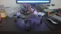
Nerevarine
Incarnate
excellent man, !!
Shah
Cyborg Agent
excellent man, !!
I actually made it for the upcoming Expo (which based on Arduino  ) in my college. Tomorrow is the demo. I am thinking of making it to dance before that. A dancing QuadBot will be cool, won't it be?
amjath
Human Spambot
Awesome!!!
OP
icebags
Technomancer
My first QuadBot and it can walk.
u're alive !! i thought arduino chip exploded while u trying to experiment iwth my untested code
 , and something happened. *s.yimg.com/lq/i/mesg/emoticons7/71.gif heck i didn't even get the courage to post here.
 anyways congrats for the quadbot, nice job.

Shah
Cyborg Agent
u're alive !! i thought arduino chip exploded while u trying to experiment iwth my untested code
anyways congrats for the quadbot, nice job.
lol. I didn't even had time to test that code. I am thinking of getting a Photodiode to make the job easier. I am lil bit busy for the next two weeks. Will test that code afterwords.
Awesome!!!
Thanks.
quagmire
Allllright !
[MENTION=129731]Shah[/MENTION] : Great job buddy. 
It would be great if you shared a video of the demo.
Nice chassis and nice use of stackable shields.
Hmm I see IR receivers and lots of servos used. Nice..
Plz give more info on your bot. Like DOF, chassis used, Servos and PWM drivers used, shields used, battery, MCU and voice thing that you're telling about.
gopi_vbboy
Cyborg Agent
[MENTION=129731]Shah[/MENTION] good...how did u make the plastic body?...is it ready made parts or you made yourself from some material by cutting?
Shah
Cyborg Agent
[MENTION=129731]Shah[/MENTION] good...how did u make the plastic body?...is it ready made parts or you made yourself from some material by cutting?
I had visited Chennai, last Thursday. I bought the chassis from there only. BTW, It was a DIY kit and it had the laser cut plates, screws, battery holder, a servo shield and 8 servos.
Replies in bold.[MENTION=129731]Shah[/MENTION] : Great job buddy.
It would be great if you shared a video of the demo.
I wish I had enough bandwidth to upload it over here.
Nice chassis and nice use of stackable shields.
I didn't design the chassis, I just bought it.
Hmm I see IR receivers and lots of servos used. Nice..
There are 8 servos and Only one of the two TSOP receivers is interfaced to control the bot using IR Remote. (I hope You can see the white Remote in the right of that pic)
Plz give more info on your bot. Like DOF, chassis used, Servos and PWM drivers used, shields used, battery, MCU and voice thing that you're telling about.
Each leg has 2DOF, Servos are SG90(TowerPro SG90 Servo Specifications and Reviews) , the Servo shield also came with the chassis. Voice thing? I don't get it. I was talking about making it to dance.
BTW, I tried to program it to dance and the first attempt failed.